Content
- 1 The Core Mechanism Behind Curved Conveyors
- 2 Tapered Roller Design and Speed Differential
- 3 Belt Material and Construction Adaptations
- 4 Drive Systems and Power Transmission
- 5 Product Stability and Tracking Control
- 6 Common Curved Conveyor Configurations
- 7 Maintenance Considerations and Wear Patterns
- 8 Engineering Calculations for Custom Curves
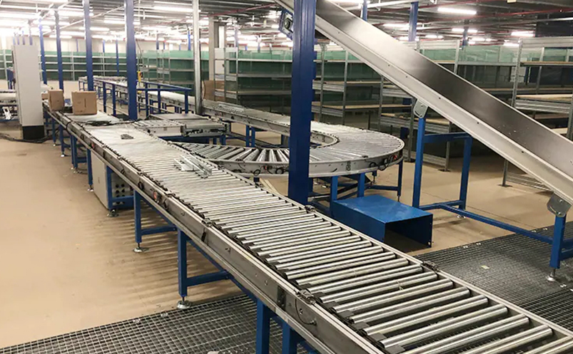
The Core Mechanism Behind Curved Conveyors
Curved conveyor belts operate by using tapered rollers or conical drums that rotate at differential speeds across the width of the belt. The inner edge of the curve travels a shorter distance than the outer edge, requiring the belt to move at different speeds simultaneously. This is achieved through precisely engineered roller geometry where each roller's diameter gradually increases from the inside radius to the outside radius, creating synchronized movement that prevents belt slippage, bunching, or stretching.
The typical curved conveyor uses a radius-to-width ratio of 2:1 or greater, meaning a 24-inch wide belt would require at minimum a 48-inch inside radius to maintain proper belt tracking and product stability. Modern systems incorporate crowned rollers, flexible belt materials, and computer-controlled drive systems to navigate turns ranging from 45 degrees to 180 degrees while maintaining consistent product positioning.
Tapered Roller Design and Speed Differential
The fundamental challenge of curved conveyors is accommodating the geometric reality that the outer edge of a turn must travel farther than the inner edge. Engineers solve this through tapered roller construction where each support roller is manufactured as a truncated cone rather than a cylinder.
Roller Geometry Calculations
For a 90-degree curve with an inside radius of 36 inches and belt width of 18 inches, the mathematics work as follows:
- Inner edge path length: 2π × 36 × (90/360) = 56.5 inches
- Outer edge path length: 2π × 54 × (90/360) = 84.8 inches
- Speed differential required: 50% faster at the outer edge
Each tapered roller must have its small diameter aligned with the inside curve and large diameter with the outside. The taper angle typically ranges from 3 to 8 degrees depending on the curve radius and belt width specifications.
Belt Material and Construction Adaptations
Standard flat conveyor belts cannot function on curves without specialized construction. Curved conveyor belts incorporate several material modifications to handle the lateral stress and differential movement.
Fabric and Compound Selection
Manufacturers use polyester-polyamide composite fabrics with cross-directional flexibility ratings 30-40% higher than standard conveyor belting. The belt must resist lateral tension on the outer edge while allowing compression on the inner edge. Thermoplastic polyurethane (TPU) covers provide the necessary flexibility with durometer hardness ratings between 85A and 95A Shore.
| Belt Type | Material Composition | Maximum Curve Angle | Typical Applications |
|---|---|---|---|
| Modular Plastic | Polypropylene/Acetal | 180° | Food processing, packaging |
| Fabric-Reinforced | Polyester/TPU | 90° | Warehousing, distribution |
| Steel-Reinforced | Steel Cable/Rubber | 45° | Heavy-duty mining, aggregate |
| Wire Mesh | Stainless Steel | 90° | Heat treatment, baking |
Edge Reinforcement Techniques
The outer edge of curved belts experiences tension forces 40-60% higher than the inner edge. Manufacturers add Kevlar or steel cable reinforcement strips along the outer 20% of belt width to prevent edge stretching and premature failure. Some designs incorporate flexible joint systems similar to tank treads, allowing independent movement of belt sections.
Drive Systems and Power Transmission
Powering a curved belt conveyor requires specialized drive configurations that account for uneven load distribution and varying friction coefficients across the belt width.
Center Drive vs. Tangential Drive
Center drive systems position the motor and drive pulley at the curved section's apex, using a crowned drive drum that matches the tapered roller profile. This configuration provides balanced power distribution but requires precise alignment. Installation tolerances must be maintained within ±0.5mm to prevent belt tracking issues.
Tangential drive systems locate the drive motor on a straight section before or after the curve, transmitting power through the belt's natural tension. This simpler design works well for curves up to 90 degrees but can cause belt slippage on tighter radius turns where the inner edge may become slack.
Variable Frequency Drive Integration
Modern curved conveyors increasingly use VFD-controlled motors with torque sensors that detect load imbalances. When product accumulates on the outer edge of a curve, sensors trigger speed adjustments to maintain even distribution. Systems from major manufacturers like Dorner and Intralox can adjust belt speed by ±15% in real-time to compensate for dynamic loading conditions.
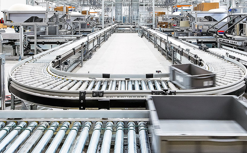
Product Stability and Tracking Control
Maintaining product position through curves presents challenges beyond simple belt movement. Items experience centrifugal forces that push them toward the outside edge unless proper countermeasures are implemented.
Centrifugal Force Mitigation
For a package traveling at 100 feet per minute through a 48-inch radius curve, the centrifugal acceleration equals:
a = v²/r = (1.67 ft/s)² / 4 ft = 0.70 ft/s²
This force must be counteracted through:
- Sidewall guides – Adjustable rails positioned 1-2 inches from product edges
- Friction-enhanced surfaces – Belt top covers with coefficient of friction above 0.6
- Banking mechanisms – Tilting the entire belt up to 15 degrees toward the inside radius
- Reduced speed zones – Automatically decreasing belt velocity by 30-40% through tight curves
Belt Tracking Sensors
Photoelectric or ultrasonic sensors monitor belt edge position at 200-500Hz sampling rates, detecting lateral drift as small as 2-3mm. When misalignment occurs, pneumatic actuators adjust guide roller angles by 0.5-2 degrees to gradually steer the belt back to center. Advanced systems use predictive algorithms that anticipate tracking errors based on load distribution patterns.
Common Curved Conveyor Configurations
Different industrial applications require specific curved conveyor geometries optimized for space constraints, throughput requirements, and product characteristics.
90-Degree Horizontal Curves
The most common configuration uses inside radii between 24-60 inches for standard package handling. Airport baggage systems extensively employ 90-degree curves with 48-inch radii to route luggage between terminals while maintaining throughput rates of 1,800-2,400 bags per hour. These systems typically use modular plastic belting with cross-rigid construction that prevents product rotation.
180-Degree Spiral Elevators
Combining curves with inclines creates spiral conveyors that elevate products while changing direction. A typical installation might rise 12-15 feet per complete 360-degree rotation using a continuous curve radius of 36-48 inches. Manufacturing facilities use these to connect production floors, achieving vertical transportation rates of 60-120 units per minute while occupying minimal floor space.
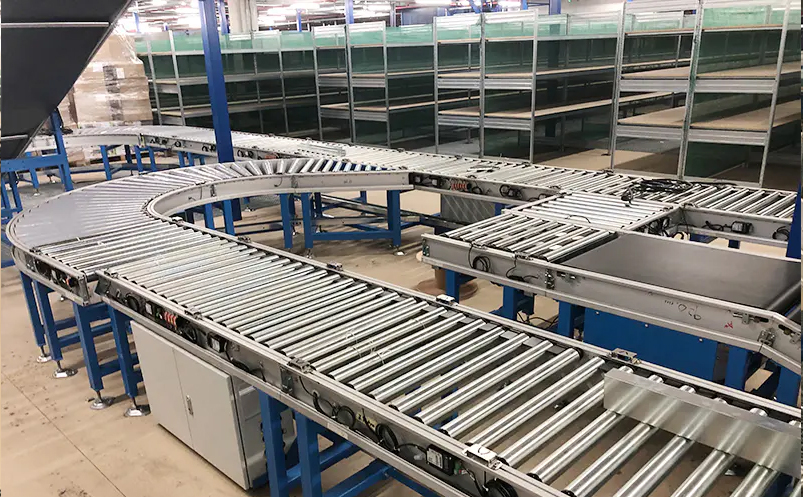
S-Curve Configurations
Reverse curves that switch from left to right require transition zones of at least 3-5 belt widths between opposing curves. Distribution centers implement S-curves to navigate around building columns or equipment while maintaining continuous flow. The transition section uses straight tangent rollers to allow the belt to normalize before entering the opposite curve direction.
Maintenance Considerations and Wear Patterns
Curved conveyors experience different failure modes than straight conveyors, requiring specialized maintenance protocols.
Differential Wear on Tapered Rollers
The larger diameter end of each tapered roller rotates faster and accumulates more bearing wear. Maintenance schedules should inspect outer edge bearings every 2,000-3,000 operating hours compared to 4,000-5,000 hours for inner edge bearings. Roller replacement typically becomes necessary when diameter variation exceeds manufacturing tolerance by more than 3mm, disrupting the designed speed differential.
Belt Edge Monitoring
The high-tension outer edge shows premature wear, with typical belt life reduced to 60-70% of straight conveyor equivalents. Weekly visual inspections should check for:
- Fraying or separation along the outer 2-3 inches of belt width
- Elongation exceeding 1-2% of original belt length
- Cover wear depth greater than 30% of original thickness
- Tracking drift requiring guide adjustment more than weekly
Lubrication Requirements
Tapered roller bearings require food-grade synthetic lubricants rated for 150-200°C operating temperatures in high-speed applications. Automated lubrication systems deliver precisely metered amounts every 500-1,000 operating hours, with outer edge bearings receiving 25-30% higher volumes to compensate for increased rotational speeds.
Engineering Calculations for Custom Curves
Designing a curved conveyor requires balancing multiple engineering constraints to achieve reliable operation.
Minimum Radius Determination
The minimum practical inside radius follows the formula: R_min = 2 × W, where W equals belt width. For a 30-inch wide belt, this yields a 60-inch minimum radius. Tighter radii cause excessive belt stress and product instability. Heavy-duty applications or high-speed systems may require ratios of 3:1 or 4:1.
Roller Spacing and Quantity
Curved sections require 30-40% more support rollers than equivalent straight sections to maintain belt support and prevent sagging. Standard roller spacing of 4-6 inches center-to-center provides adequate support for light to medium loads. Heavy products or loose materials require tighter 2-3 inch spacing to prevent belt deformation between rollers.
Power Requirements
Friction losses in curves increase motor power needs by 40-70% compared to straight conveyors of equal length. A 90-degree curve with 48-inch radius requires similar power to a straight section 12-15 feet long. Engineers must account for:
- Bearing friction on larger diameter roller ends
- Belt flexing resistance through the curve
- Product resistance to directional change
- Additional guide rail friction from product contact