Content
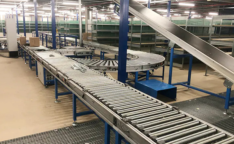
A gravity roller conveyor moves products from point A to point B without a single watt of electricity. No motor, no controller, no power bill — just physics doing the work. That simplicity is why warehouses, distribution centers, and production lines around the world rely on them. But building one that actually works requires more than bolting some rollers onto a frame. Here is a practical breakdown of how to make a gravity roller conveyor that performs reliably from day one.
Understand the Core Principle First
Gravity roller conveyors move items because the frame is inclined. Products sitting on the rollers are pulled downhill by gravity, overcoming the rolling resistance of the bearings. The system works only if that gravitational force exceeds friction — which means slope calculation is the single most critical design decision you will make.
The standard minimum slope is 5° of incline, roughly equivalent to a 100 mm height drop per 1,000 mm of conveyor length. Lighter loads need more slope; heavier loads with smooth, rigid bottoms need less. Products must always contact at least three rollers at once — if your load spans fewer than three rollers, it will tip, jam, or stall.
Step 1 — Define Your Load Parameters
Before selecting a single component, nail down four numbers:
- Maximum load weight — this drives roller capacity and frame strength
- Product footprint dimensions — length and width determine roller spacing and conveyor width
- Bottom surface type — rigid flat bottoms (cartons, totes) flow easily; soft or irregular bottoms require more slope and closer roller spacing
- Throughput speed required — dictates final slope angle and whether you need speed-retarding accessories
Conveyor width is typically product width plus 50–100 mm of clearance on each side. Roller spacing should be no more than one-third of the shortest product length — so a 300 mm box needs rollers no more than 100 mm apart.
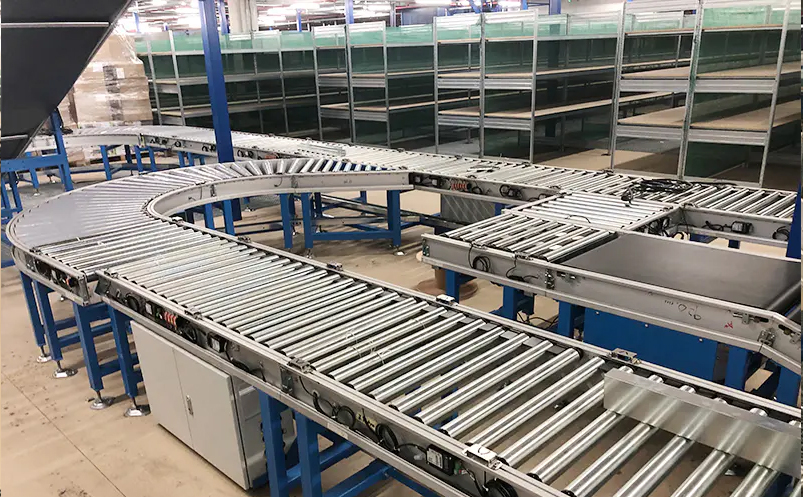
Step 2 — Build the Frame
The frame is the backbone. Steel tube frames handle heavy industrial loads; aluminum roller conveyor options suit lighter-duty applications where weight, corrosion resistance, or frequent reconfiguration matters. Cut your side rails to the required length, connect them with cross-members at both ends and at regular intervals along the span, and verify the frame is square and level before installing anything else.
Adjustable legs are strongly recommended. They allow you to dial in exact slope during commissioning and make it easy to adapt if load characteristics change later. Install legs every 1.5 to 2 meters along the conveyor length for adequate support.
Step 3 — Select and Install the Rollers
Roller diameter, material, and bearing type all affect performance. Steel rollers in the 50–89 mm diameter range handle most medium-duty warehouse applications. For environments where product contact or hygiene matters, steel-free roller conveyor solutions using resin or plastic shells are a better fit.
Install rollers by dropping their spring-loaded shaft ends into the punched slots on the frame rails. Verify that every roller sits parallel to its neighbors — a misaligned roller will cause products to veer sideways or jam. Spacing should be consistent across the full conveyor length, not just approximate.
Bearings should be sealed and pre-greased for minimal maintenance. Open bearings roll faster initially but collect dust and fail sooner in real facility conditions.
Step 4 — Set the Slope Correctly
This step determines whether your conveyor works or frustrates you. Set the incline using your adjustable legs, targeting the minimum slope that reliably moves your lightest load. Then test with your heaviest load to confirm it does not accelerate out of control.
The practical rule: pitch recommendations range from 50 mm to 200 mm of drop per 3-meter section, depending on load type and roller bearing style. Grease-packed bearings create more rolling resistance and may need slightly more slope than open bearings. Always test before committing to a final configuration.
If products move too fast at the required slope, install retarding rollers, rubber-coated rollers, or an end stop at the discharge point. If they stall, increase slope or reduce roller spacing. Gravity conveyor design is iterative — build in adjustment room.
Step 5 — Add Guides, Stops, and Safety Features
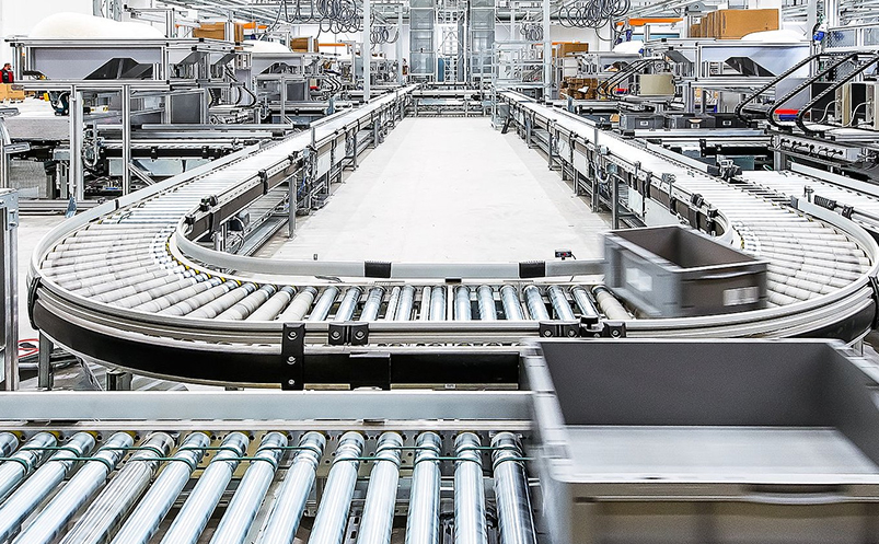
Side guides (typically 50–100 mm high) prevent products from falling off the conveyor, especially on curves or at merge points. An end stop at the discharge end prevents products from running off the line and provides a controlled accumulation point.
For operations where products need to pause mid-line without a full shutdown, consider integrating the gravity section with an accumulating roller conveyor system at critical zones. This combination lets products buffer between workstations without manual intervention.
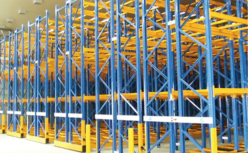
In gravity rack storage applications, the same roller principles apply within shelving bays — products load from one end and flow to the pick face automatically, enabling FIFO rotation without powered assistance.
Key Design Parameters at a Glance
| Parameter | Typical Range | Notes |
|---|---|---|
| Minimum slope | 5° / 100 mm per 1,000 mm | Starting point; adjust per load |
| Roller spacing | ≤ 1/3 of shortest product length | Minimum 3 rollers under load at all times |
| Conveyor width | Product width + 50–100 mm | More clearance for irregular loads |
| Support leg interval | Every 1.5–2 m | Adjustable legs preferred |
| Roller diameter | 50–89 mm (medium-duty) | Larger diameters for heavier loads |
Common Mistakes to Avoid
Three mistakes account for most gravity conveyor failures in the field. First, undersizing roller capacity — always calculate the load per roller (total load ÷ number of rollers simultaneously supporting it) and verify it falls within the roller's rated capacity. Second, ignoring the acceleration effect — a roller still spinning from the previous box will push the next one faster than expected, causing end-of-line collisions without a proper stop mechanism. Third, skipping the test phase — slope requirements in the real world often differ from paper calculations because packaging materials, bearing condition, and facility temperature all affect friction.
For a complete range of roller conveyor products suited to gravity applications — including frames, rollers, and accessories — verify specifications against your actual load data before ordering. A well-matched system requires minimal adjustment on installation and delivers years of low-maintenance operation.